Thursday, September 3, 2020

STM32F103R6 Simple 2-Digit Multiplexing Display And Switch Example

Multiplexing display could save the amount of micro-controller digital output comparing to a conventional individual 7-Segment display driving. Each digits are activated for a few Milli-seconds. We can multiplex up to 8 digits of 7-Segment display for convenient. 
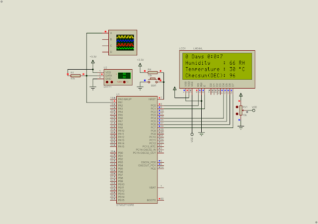
STM32F103R6 Simple 2-Digit Multiplexing Display And Switch Example
Simulating Program
In this example, I use the STM32F103R6 to multiplex a two-digit common cathode 7-Segment display. An input switch used for input counting. It will count up to 0x0F as it pressed. It's active low. 

STM32F103R6 Simple 2-Digit Multiplexing Display And Switch Example

Pin configurations

 I use HAL_Delay function of STM32 HAL driver to activate each digits for 5 Milli-seconds. Each time the SW2 button is pressed it will wait for 150 Milli-seconds before updating the counting values. Hence it causes display flickering.

  1. /* USER CODE BEGIN Header */
  2. /**
  3.   ******************************************************************************
  4.   * @file : main.c
  5.   * @brief : Main program body
  6.   ******************************************************************************
  7.   * @attention
  8.   *
  9.   * <h2><center>&copy; Copyright (c) 2022 STMicroelectronics.
  10.   * All rights reserved.</center></h2>
  11.   *
  12.   * This software component is licensed by ST under BSD 3-Clause license,
  13.   * the "License"; You may not use this file except in compliance with the
  14.   * License. You may obtain a copy of the License at:
  15.   * opensource.org/licenses/BSD-3-Clause
  16.   *
  17.   ******************************************************************************
  18.   */
  19. /* USER CODE END Header */
  20. /* Includes ------------------------------------------------------------------*/
  21. #include "main.h"
  22.  
  23. /* Private function prototypes -----------------------------------------------*/
  24. void SystemClock_Config(void);
  25. static void MX_GPIO_Init(void);
  26. /* USER CODE BEGIN PFP */
  27.  
  28. /*7-Segment Display Code*/
  29. void ssdAssign(unsigned char _data);
  30.  
  31. const unsigned char dAnode[10]={0xC0,0xF9,0xA4,0xB0,0x99,0x92,0x82,0xF8,0x80,0x90};
  32. char temp=0,gpioNum=0x01,cnt=0;
  33.  
  34. int main(void)
  35. {
  36. /* Reset of all peripherals, Initializes the Flash interface and the Systick. */
  37. HAL_Init();
  38.  
  39. /* USER CODE BEGIN Init */
  40.  
  41. /* USER CODE END Init */
  42.  
  43. /* Configure the system clock */
  44. SystemClock_Config();
  45.  
  46. /* USER CODE BEGIN SysInit */
  47.  
  48. /* USER CODE END SysInit */
  49.  
  50. /* Initialize all configured peripherals */
  51. MX_GPIO_Init();
  52. /* USER CODE BEGIN 2 */
  53.  
  54. /* USER CODE END 2 */
  55.  
  56. /* Infinite loop */
  57. /* USER CODE BEGIN WHILE */
  58. while (1)
  59. {
  60. /*Check if the input button is pressed*/
  61. if(HAL_GPIO_ReadPin(GPIOC,GPIO_PIN_12)==0){
  62. cnt++;
  63. HAL_Delay(150);
  64. }
  65. if(cnt>99) cnt=0;
  66.  
  67. /*Multiplexing Display Process*/
  68. HAL_GPIO_WritePin(GPIOC,GPIO_PIN_8|GPIO_PIN_9,GPIO_PIN_RESET);
  69. ssdAssign(cnt/10);
  70. HAL_GPIO_WritePin(GPIOC,GPIO_PIN_8,GPIO_PIN_SET);
  71. HAL_Delay(5);
  72.  
  73. HAL_GPIO_WritePin(GPIOC,GPIO_PIN_8|GPIO_PIN_9,GPIO_PIN_RESET);
  74. ssdAssign(cnt%10);
  75. HAL_GPIO_WritePin(GPIOC,GPIO_PIN_9,GPIO_PIN_SET);
  76. HAL_Delay(5);
  77.  
  78. }
  79. /* USER CODE END 3 */
  80. }
  81.  
  82. void ssdAssign(unsigned char _data){
  83. /*seven-segment display processing*/
  84. gpioNum=0x01;
  85. temp=0x01;
  86. for(int i=0;i<8;i++){
  87. HAL_GPIO_WritePin(GPIOC,gpioNum,dAnode[_data]&temp);
  88. gpioNum<<=1;
  89. temp<<=1;
  90. }
  91. }
  92.  
  93. /**
  94.   * @brief System Clock Configuration
  95.   * @retval None
  96.   */
  97. void SystemClock_Config(void)
  98. {
  99. RCC_OscInitTypeDef RCC_OscInitStruct = {0};
  100. RCC_ClkInitTypeDef RCC_ClkInitStruct = {0};
  101.  
  102. /** Initializes the RCC Oscillators according to the specified parameters
  103.   * in the RCC_OscInitTypeDef structure.
  104.   */
  105. RCC_OscInitStruct.OscillatorType = RCC_OSCILLATORTYPE_HSI;
  106. RCC_OscInitStruct.HSIState = RCC_HSI_ON;
  107. RCC_OscInitStruct.HSICalibrationValue = RCC_HSICALIBRATION_DEFAULT;
  108. RCC_OscInitStruct.PLL.PLLState = RCC_PLL_NONE;
  109. if (HAL_RCC_OscConfig(&RCC_OscInitStruct) != HAL_OK)
  110. {
  111. Error_Handler();
  112. }
  113. /** Initializes the CPU, AHB and APB buses clocks
  114.   */
  115. RCC_ClkInitStruct.ClockType = RCC_CLOCKTYPE_HCLK|RCC_CLOCKTYPE_SYSCLK
  116. |RCC_CLOCKTYPE_PCLK1|RCC_CLOCKTYPE_PCLK2;
  117. RCC_ClkInitStruct.SYSCLKSource = RCC_SYSCLKSOURCE_HSI;
  118. RCC_ClkInitStruct.AHBCLKDivider = RCC_SYSCLK_DIV1;
  119. RCC_ClkInitStruct.APB1CLKDivider = RCC_HCLK_DIV1;
  120. RCC_ClkInitStruct.APB2CLKDivider = RCC_HCLK_DIV1;
  121.  
  122. if (HAL_RCC_ClockConfig(&RCC_ClkInitStruct, FLASH_LATENCY_0) != HAL_OK)
  123. {
  124. Error_Handler();
  125. }
  126. }
  127.  
  128. /**
  129.   * @brief GPIO Initialization Function
  130.   * @param None
  131.   * @retval None
  132.   */
  133. static void MX_GPIO_Init(void)
  134. {
  135. GPIO_InitTypeDef GPIO_InitStruct = {0};
  136.  
  137. /* GPIO Ports Clock Enable */
  138. __HAL_RCC_GPIOC_CLK_ENABLE();
  139. __HAL_RCC_GPIOA_CLK_ENABLE();
  140.  
  141. /*Configure GPIO pin Output Level */
  142. HAL_GPIO_WritePin(GPIOC, GPIO_PIN_0|GPIO_PIN_1|GPIO_PIN_2|GPIO_PIN_3
  143. |GPIO_PIN_4|GPIO_PIN_5|GPIO_PIN_6|GPIO_PIN_7
  144. |GPIO_PIN_8|GPIO_PIN_9, GPIO_PIN_RESET);
  145.  
  146. /*Configure GPIO pins : PC0 PC1 PC2 PC3
  147.   PC4 PC5 PC6 PC7
  148.   PC8 PC9 */
  149. GPIO_InitStruct.Pin = GPIO_PIN_0|GPIO_PIN_1|GPIO_PIN_2|GPIO_PIN_3
  150. |GPIO_PIN_4|GPIO_PIN_5|GPIO_PIN_6|GPIO_PIN_7
  151. |GPIO_PIN_8|GPIO_PIN_9;
  152. GPIO_InitStruct.Mode = GPIO_MODE_OUTPUT_PP;
  153. GPIO_InitStruct.Pull = GPIO_NOPULL;
  154. GPIO_InitStruct.Speed = GPIO_SPEED_FREQ_LOW;
  155. HAL_GPIO_Init(GPIOC, &GPIO_InitStruct);
  156.  
  157. /*Configure GPIO pin : PC12 */
  158. GPIO_InitStruct.Pin = GPIO_PIN_12;
  159. GPIO_InitStruct.Mode = GPIO_MODE_INPUT;
  160. GPIO_InitStruct.Pull = GPIO_PULLUP;
  161. HAL_GPIO_Init(GPIOC, &GPIO_InitStruct);
  162.  
  163. }
  164.  
  165. /* USER CODE BEGIN 4 */
  166.  
  167. /* USER CODE END 4 */
  168.  
  169. /**
  170.   * @brief This function is executed in case of error occurrence.
  171.   * @retval None
  172.   */
  173. void Error_Handler(void)
  174. {
  175. /* USER CODE BEGIN Error_Handler_Debug */
  176. /* User can add his own implementation to report the HAL error return state */
  177. __disable_irq();
  178. while (1)
  179. {
  180. }
  181. /* USER CODE END Error_Handler_Debug */
  182. }
  183.  
  184. #ifdef USE_FULL_ASSERT
  185. /**
  186.   * @brief Reports the name of the source file and the source line number
  187.   * where the assert_param error has occurred.
  188.   * @param file: pointer to the source file name
  189.   * @param line: assert_param error line source number
  190.   * @retval None
  191.   */
  192. void assert_failed(uint8_t *file, uint32_t line)
  193. {
  194. /* USER CODE BEGIN 6 */
  195. /* User can add his own implementation to report the file name and line number,
  196.   ex: printf("Wrong parameters value: file %s on line %d\r\n", file, line) */
  197. /* USER CODE END 6 */
  198. }
  199. #endif /* USE_FULL_ASSERT */
  200.  
  201. /************************ (C) COPYRIGHT STMicroelectronics *****END OF FILE****/
  202.  

Click here to download its source file. 


For other similar posts please check,

  1. Getting Started With STM32F103C8T6 Module with STM32CubeIDE
  2.  STM32F103C8T6 Blue Pill SysTick and Multiplexing Display Example
  3.  STM32F103C8T6 Blue Pill Switch And Multiplexing Display Interface Using SysTick
  4.  STM32F103C8T6 Blue Pill SysTick LED Blinking
  5. STM32F103R6 Common Anode Seven Segments Display Example 
  6. STM32F103R6 Common Anode Seven Segments Display And Switch Interfacing 
  7. STM32F103R6 Simple 2-Digit Multiplexing Display And Switch Example 
  8. STM32F103R6 SysTick And Digital Clock Example 

No comments:

Post a Comment